

How the Lube Oil Cooler Works in a Turbine System
The cooler is a central component of the closed-loop lube oil system. The typical flow is:
- Sump: Oil drains into a reservoir (sump tank).
- Pumps: Main and auxiliary (emergency) pumps push the oil through the system.
- Cooling: The warm oil (typically coming from the bearings at ~150-160°F / 65-71°C) is directed through the oil cooler.
- Heat Exchange: The cooler transfers the heat from the oil to a cooling medium.
- Filtration: The now-cooled oil (target temperature ~120-130°F / 49-54°C) passes through filters to remove any contaminants.
- Return: The clean, cool oil is supplied back to the bearings and control systems.
This cycle is continuous, maintaining a stable and safe oil temperature.
Types of Coolers Used in Turbines
Due to the critical nature of turbines, their cooling systems are highly reliable and often redundant.
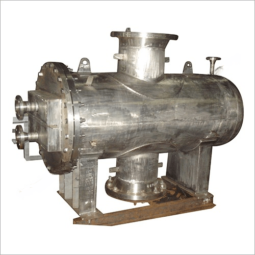
1. Water-Cooled Heat Exchanger (Most Common)
- How it works: Uses a shell-and-tube design. Hot oil is pumped through the tubes, while cool water from a separate cooling water system (e.g., a cooling tower, river, or sea water) flows around the tubes inside the shell.
- Advantage: Highly efficient and provides very stable temperature control.
- Consideration: Requires a reliable source of cool water. There is a risk of internal leakage, where water contaminates the oil. To monitor for this, the oil is constantly checked for clarity and water content.
2. Air-Cooled Oil Cooler (Oil-to-Air)
- How it works: Similar to a car radiator. Oil flows through finned tubes, and one or more fans force air across the fins to carry heat away.
- Advantage: No risk of water-oil mixing. Self-contained.
- Disadvantage: Cooling efficiency is less consistent and depends on ambient air temperature. It is larger and can be louder.
- Application: Often used in mobile gas turbines or as a secondary cooler.
Key Design and Operational Features
Turbine lube oil systems are engineered for maximum reliability:
- Redundancy: Critical turbines almost always have two coolers in parallel (100% redundancy). Valving allows one cooler to be isolated for maintenance or cleaning while the other remains in operation, ensuring the turbine never runs without cooling.
- Temperature Control: A temperature control valve (3-way thermostatic valve) automatically bypasses the cooler when the oil is cold during startup. As the oil warms up, the valve gradually directs more and more flow through the cooler to maintain the perfect outlet temperature.
- Monitoring: Operators constantly monitor lube oil temperature in and out of the cooler and bearing metal temperatures. Any rising trend is an immediate alarm.
Consequences of Cooler Failure or Fouling
- Fouling (Internal): Scale, sludge, or varnish buildup inside the cooler tubes acts as an insulator. This reduces heat transfer, causing rising oil temperatures and triggering alarms.
- Fouling (External – Water side): Scaling or biological growth on the water side of the tubes has the same effect: reduced cooling and high oil temps.
- Leakage: An internal leak allowing water into the oil is a serious emergency. Water degrades lubrication, promotes corrosion, and can cause a catastrophic bearing failure. The unit must be shut down immediately.
Maintenance Importance
Maintenance is proactive and rigorous:
- Regular Cleaning: The water side is cleaned chemically to prevent scaling. The oil side is monitored for degradation.
- Oil Analysis: Routine oil analysis checks for water content, viscosity, and particulates, which can provide early warning of cooler problems.
- Performance Testing: Heat transfer performance is monitored to identify fouling before it becomes critical.