

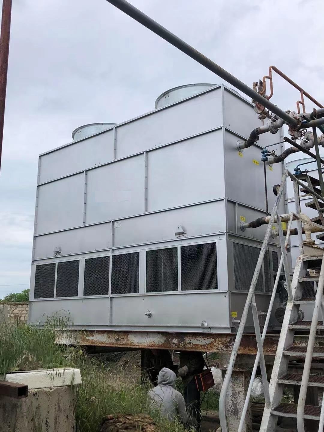
Counter Flow Closed Circuit cooling Tower
Counter Flow Closed Circuit Cooling Tower is a highly efficient hybrid cooling system that combines the process protection of a closed loop with the thermal efficiency of evaporative cooling and the design advantages of counter-flow air/water contact.
In this design:
- Air flows vertically upward.
- Spray water flows vertically downward over the outside of the coil.
- These two flows are in direct opposition (counter-flow) to each other.
- The process fluid flows inside the coil, completely separate and protected.
This counter-flow arrangement is key to its performance.
How It Works: Step-by-Step
- Hot Process Fluid In: The warm process fluid (e.g., water, glycol mix) from the system enters the closed circuit cooling tower and flows through the internal coil bundle.
- Spray Water Distribution: A separate pump draws water from the cold water basin and sprays it evenly over the external surface of the coil.
- Air Flow (Counter-Flow): A fan at the top of the unit (induced draft) draws ambient air vertically upward through the tower. This air moves directly against the downward flow of the spray water.
- Evaporation and Heat Transfer:
- As air and water meet in counter-flow, a portion of the spray water evaporates.
- The energy for evaporation is drawn from the remaining spray water, chilling it significantly.
- This chilled spray water film on the outside of the coil efficiently absorbs heat from the hot process fluid inside the coil.
- The counter-flow design ensures that the coldest air (entering at the bottom) meets the coldest spray water (dripping off the coil), and the hottest air (exhausting at the top) meets the warmest spray water (just after it’s sprayed). This maximizes the temperature difference (delta T) throughout the entire heat transfer surface, which is the principle of optimal thermal efficiency.
- Cooled Process Fluid Out: The now-cooled process fluid exits the coil and returns to the process it serves (e.g., a chiller, laser, machine tool).
- Air and Water Exit: The warmed, moist air is exhausted out the top by the fan. The spent spray water drips down into the basin to be recirculated, with a small amount bled off to control mineral concentration.
Key Components:
- Coil Bundle: The heart of the system, typically made of carbon steel (with a protective coating) or stainless steel for corrosion resistance.
- Induced Draft Fan: Located at the top of the unit to draw air vertically upward.
- Spray Nozzles: Evenly distribute water over the coil surface.
- Eliminators: Prevent water droplets (drift) from being carried out of the tower with the exhaust air.
- Sump and Pump: The basin that collects spray water and the pump that recirculates it.