

EM Baffles Heat Exchangers:
Overview:
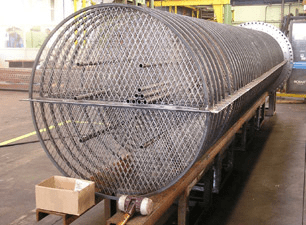
EM Baffles Heat Exchangers technology offers a step change in shell and tube type heat exchanger design. Expanded metal baffles (tube supports) create an open structure allowing for longitudinal flow at the shell side. Stagnant or ‘dead zones’ found in traditional segmental baffle heat exchangers, which tend to foul rapidly, are not present in EM baffles heat exchangers. Tube vibration is also eliminated due to the longitudinal flow characteristics and pressure drop is lowered.
Process:
Principles of EM Baffles heat exchangers are open flow structure of the baffle allows the shell side fluid to flow along the tubes, but in the vicinity of the baffles the flow area is constricted, creating local turbulence and velocity increase in the flow while breaking up the boundary layer over the tubes. The unique grid shape induces a local cross flow component on top of the longitudinal bulk flow pattern which, together with the localised turbulent flow, improves the heat transfer characteristics at the surface of the tubes. The breakup of the boundary layer occurs repeatedly at each expanded metal baffle along the length of the heat exchanger, resulting in lower hydraulic resistance while maintaining heat transfer. Pressure loss is effectively converted into improved heat transfer and, compared with the segmental baffle, heat transfer at the same fluid velocity is significantly higher.
image:
Benefits:
- Elimination of damaging flow-induced tube vibration
- Lower pressure drop on the shell side
- Improved heat transfer capabilities
- Lower fouling rates
- Lower energy consumption and reduced emissions
- Competitive manufacturing costs
- Lower fouling rate
- Elimination of damaging flow-induced tube vibration
- Improved heat transfer capabilities
- Competitive manufacturing cost
- Large operating window
- Applicable in combination with segmental baffle
- Lower temperature approach
- Uniform flow pattern at shell side• possible CO2 reduction
- Reduced weight of heat exchanger
- Compact heat exchanger design.
Features:
- Large, gas-piston assisted, loading door
2. Inverted cone-shaped loading chamber promotes wood free-fall without ‘bridging’
3. Loading chamber, the most vulnerable part of any wood boiler, is 10 to 20 mm thick. (3/8″ to7/8″)
4. Ceramic honey-combed is readily accessible for easy ash removal.
5. Robust embossed aluminum boiler jacket.
6. Primary & secondary air preheated by passing under cyclonic combustion chamber.
7. Secondary combustion chamber. CO and organics consumed.
8. Primary air intake – actuator driven. Closed off when loading wood to eliminate smoke rollback
9. Pre-heated secondary air blended with wood gas at entry to secondary combustion chamber.
10. Flue gas temperature based thermo-difference control monitors and regulates combustion.
Applications:
- Food processing industries
- Textile industries
- Sugar Industries
- Drier industries
- Cement plant industries.
- Hot water air heater / hot water radiator
- Air heater for fluid bed dryers