

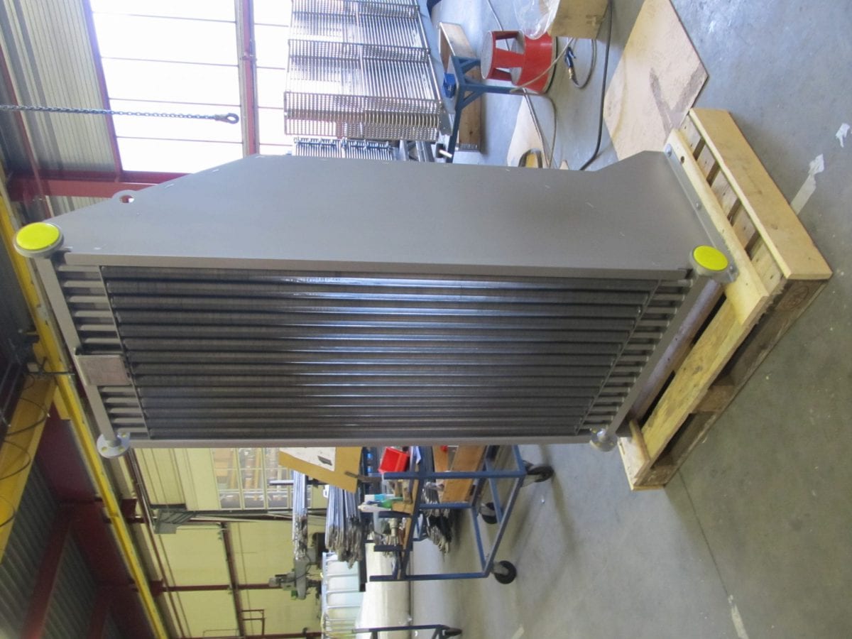
ypes of Fins Used in Air-Cooled Heat Exchangers (ACHEs)
Fins are critical components in air-cooled heat exchangers, significantly enhancing heat transfer efficiency by increasing the surface area exposed to cooling air. Different fin types are used based on application requirements, thermal performance needs, and environmental conditions.
Basic Fin Types
A. Plain Fins (Flat Fins)
- Design: Simple, flat, continuous metal strips
- Advantages:
- Low cost
- Easy to manufacture
- Low air-side pressure drop
- Disadvantages:
- Lower heat transfer efficiency compared to enhanced fins
- Applications:
- Low-fouling environments
- General-purpose cooling
B. Serrated Fins (Cut Fins)
- Design: Plain fins with periodic cuts/serrations
- Advantages:
- Better turbulence → higher heat transfer
- Good balance between performance and pressure drop
- Disadvantages:
- More susceptible to fouling than plain fins
- Applications:
- Petrochemical plants
- Power generation
C. Louvered Fins
- Design: Angled cuts create small deflectors
- Advantages:
- Excellent heat transfer (disrupts boundary layer)
- Compact design
- Disadvantages:
- Higher air-side pressure drop
- Prone to clogging in dirty environments
- Applications:
- Automotive radiators
- HVAC systems
D. Wavy Fins
- Design: Corrugated/undulating surface
- Advantages:
- Improved heat transfer via increased turbulence
- Lower fouling tendency than serrated fins
- Disadvantages:
- Moderate pressure drop increase
- Applications:
- Industrial process cooling
- Compressed air systems
E. Pin Fins
- Design: Discrete pins protruding from tube surface
- Advantages:
- Very high heat transfer in low-velocity air
- Good for omnidirectional airflow
- Disadvantages:
- High pressure drop
- Difficult to clean
- Applications:
- Electronics cooling
- Aerospace heat exchangers
2. Specialized Fin Designs
A. Studded Fins
- Design: Metal studs welded to tubes
- Used in: High-temperature applications (e.g., boiler exhaust)
B. Embedded Fins
- Design: Fins mechanically bonded into grooves
- Used in: High-pressure/temperature services
C. Spiral Fins
- Design: Continuous helical fin around tube
- Used in: Gas-to-air applications
3. Fin Material Selection
| Material | Temperature Limit | Corrosion Resistance | Typical Use |
| Aluminum | 150°C | Good | HVAC, general industrial |
| Copper | 200°C | Excellent | Refrigeration |
| Carbon Steel | 400°C | Poor | High-temp industrial |
Thermal Performance Impact
A. Heat Transfer Enhancement
- Higher FPI → Larger surface area → Increased heat transfer capacity
- Example: Increasing from 8 FPI to 12 FPI can boost heat transfer by 20-30%
- Diminishing returns at very high densities (boundary layer effects)
3. Airside Pressure Drop Effects
A. Direct Relationship
- Higher FPI → Greater airflow resistance → Higher ΔP
- 10 FPI → ΔP ≈ 0.5″ H₂O
- 14 FPI → ΔP ≈ 1.2″ H₂O (typical)
B. Fan Power Consequences
- P ∝ (ΔP)^1.5 → Small ΔP increases require significantly more fan power
- Rule of thumb: Every 0.1″ H₂O ΔP increase → +2-3% fan energy
4. Fouling & Maintenance Considerations
| Fin Density | Fouling Risk | Cleanability |
| Low (3-8 FPI) | Low | Easy |
| Medium (8-12 FPI) | Moderate | Moderate |
| High (12-16+ FPI) | High | Difficult |
- High FPI units in dirty environments:
- 30-50% performance degradation possible in 6-12 months
- Require frequent cleaning (water jets, compressed air)
5. Economic Trade-offs
| Parameter | High FPI | Low FPI |
| Initial Cost | Higher (more material) | Lower |
| Footprint | Smaller | Larger |
| Energy Cost | Higher (fan power) | Lower |
| Maintenance Cost | Higher | Lower |
6. Optimal Fin Density Selection
A. For Clean Air Applications (HVAC, data centres)
- Recommended: 12-16 FPI
- Rationale: Maximize compactness, fouling unlikely
B. For Industrial/Dirty Air (Petrochemical, power plants)
- Recommended: 6-10 FPI
- Rationale: Balance performance with cleanability
C. For High-Temperature Services (>300°C)
- Recommended: 4-8 FPI
- Rationale: Accommodate thermal expansion
7. Advanced Considerations
A. Variable Fin Density Designs
- Front rows: Lower FPI (handle initial dirt loading)
- Rear rows: Higher FPI (cleaner air available)
B. Fin Density vs. Fin Height
- Taller fins can compensate for lower FPI
- Example: 8 FPI × 1″ fins ≈ 12 FPI × 0.5″ fins in surface area
C. Modern Computational Optimization
- CFD modelling to find ideal FPI for:
- Minimum life-cycle cost
- Specific fouling conditions
- Variable speed fan operation
8. Practical Example: Refinery Application
- Conditions: Cooling hydrocarbon vapor, moderate fouling
- Selected Design:
- 10 FPI serrated aluminum fins
- 3-row configuration
- Automatic louver controls
- Result:
- 5-year cleaning interval
- 12% lower lifetime cost vs. 14 FPI design
Fin density represents a crucial compromise between thermal performance and operational practicality. While high FPI increases heat transfer, it escalates pressure drop, fan power, and fouling risks. Optimal selection requires balancing:
- Thermal requirements
- Air cleanliness
- Energy costs
- Maintenance capabilities
For your specific application, would you like assistance in performing a fin density optimization analysis? I can help evaluate trade-offs between 8/10/12 FPI configurations based on your operating conditions.