

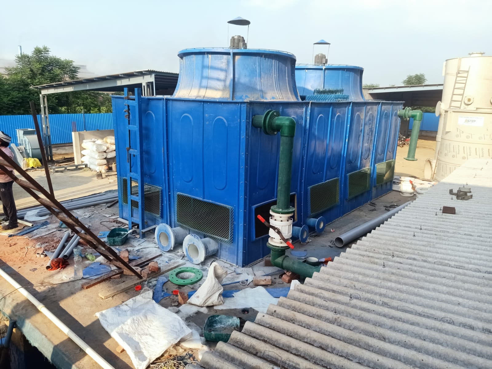
A Forced Draft, Counter Flow Cooling Tower is a mechanical draft cooling tower where air is pushed (forced) into the tower by a fan located at the air inlet, and the flow of air is in the opposite direction to the flow of falling water.
. How It Works (Step-by-Step)
- Hot Water Inlet: Hot water from the industrial process (e.g., from a condenser or heat exchanger) is pumped to the top of the tower.
- Water Distribution: The water is evenly distributed over the fill media (packing) via a system of spray nozzles or troughs.
- Water Flow: The water then trickles downward through the fill media. The fill’s purpose is to create a large surface area for air-water contact.
- Air Flow (The “Forced Draft”):
- A centrifugal or axial fan, located at the base (bottom) of the tower on the air inlet side, forces ambient air into the tower.
- This air is pushed upwards through the fill media.
- Heat & Mass Transfer (The “Counter Flow”):
- As the air moves UP and the water moves DOWN, they come into direct contact in a counter-current arrangement.
- This is the most thermally efficient configuration because the coolest air (entering from the bottom) meets the coolest water (exiting at the bottom), and the hottest, most humid air (exiting at the top) meets the hottest water (entering at the top).
- Evaporation of a small portion of the water removes latent heat, cooling the remaining water.
- Cooled Water Collection: The now-cooled water collects in the cold water basin at the bottom of the tower and is returned to the process.
- Air/Drift Elimination: The warm, moist air is discharged vertically from the top of the tower. Drift eliminators prevent water droplets from being carried out with the exhaust air.
2. Key Components
- Fan & Motor Assembly: Located at the air inlet(s), typically on the sides or bottom. Forced draft fans handle cooler, denser air.
- Fill Media: Plastic, wood, or PVC sheets arranged to maximize surface area and contact time. Can be splash-type (breaks water into droplets) or film-type (spreads water into thin sheets).
- Water Distribution System: Piping, valves, and nozzles at the top.
- Drift Eliminators: Usually at the air outlet (top) to reduce water loss.
- Cold Water Basin: Sump at the bottom.
- Structure: Casing (often FRP for corrosion resistance) and supports.
- Louvers: At the air inlets to distribute air evenly and prevent water splash-out.
3. Advantages
- Fan Protection: The fan handles cooler, drier ambient air. This leads to less corrosion, erosion, and fatigue on the fan blades and motor.
- Stable Airflow: Air entry is less susceptible to recirculation issues because it is forced in at a positive pressure.
- Easier Maintenance: Major mechanical components (fan, drive, motor) are at ground/access level, making inspection and maintenance safer and easier.
- Good Performance in High Ambient Conditions: Can maintain stable airflow even in hot, still conditions.
- Compact Footprint: Often more compact than induced draft designs for a given capacity.
Comparison with Induced Draft Counter Flow Towers
| Feature | Forced Draft | Induced Draft |
| Fan Location | At air inlet (bottom/side) | At air outlet (top) |
| Air Pressure in Fill | Positive | Negative (drawing/suction) |
| Fan Air Handled | Cool, dense ambient air | Hot, humid saturated air |
| Maintenance Access | Excellent (ground level) | Poor (requires climbing or platform) |
| Fan Corrosion/Erosion | Lower risk | Higher risk (wet, corrosive air) |
| Exit Air Velocity | Low | High, reducing recirculation risk |
| Power Consumption | Typically higher | Typically lower for same duty |
| Icing Problem Area | Water distribution (top) | Cold water basin & fill (bottom) |
6. Common Applications
- HVAC Systems for large buildings, districts, or hospitals.
- Power Plants (smaller to medium units, or as auxiliary cooling).
- Chemical & Processing Plants where maintenance accessibility is critical.
- Manufacturing Facilities (plastic injection molding, metalworking, etc.).
- Often preferred in installations where fan noise must be contained within the tower structure.