

Heat Exchanger Suitable for High pressure, temperature, large duties?
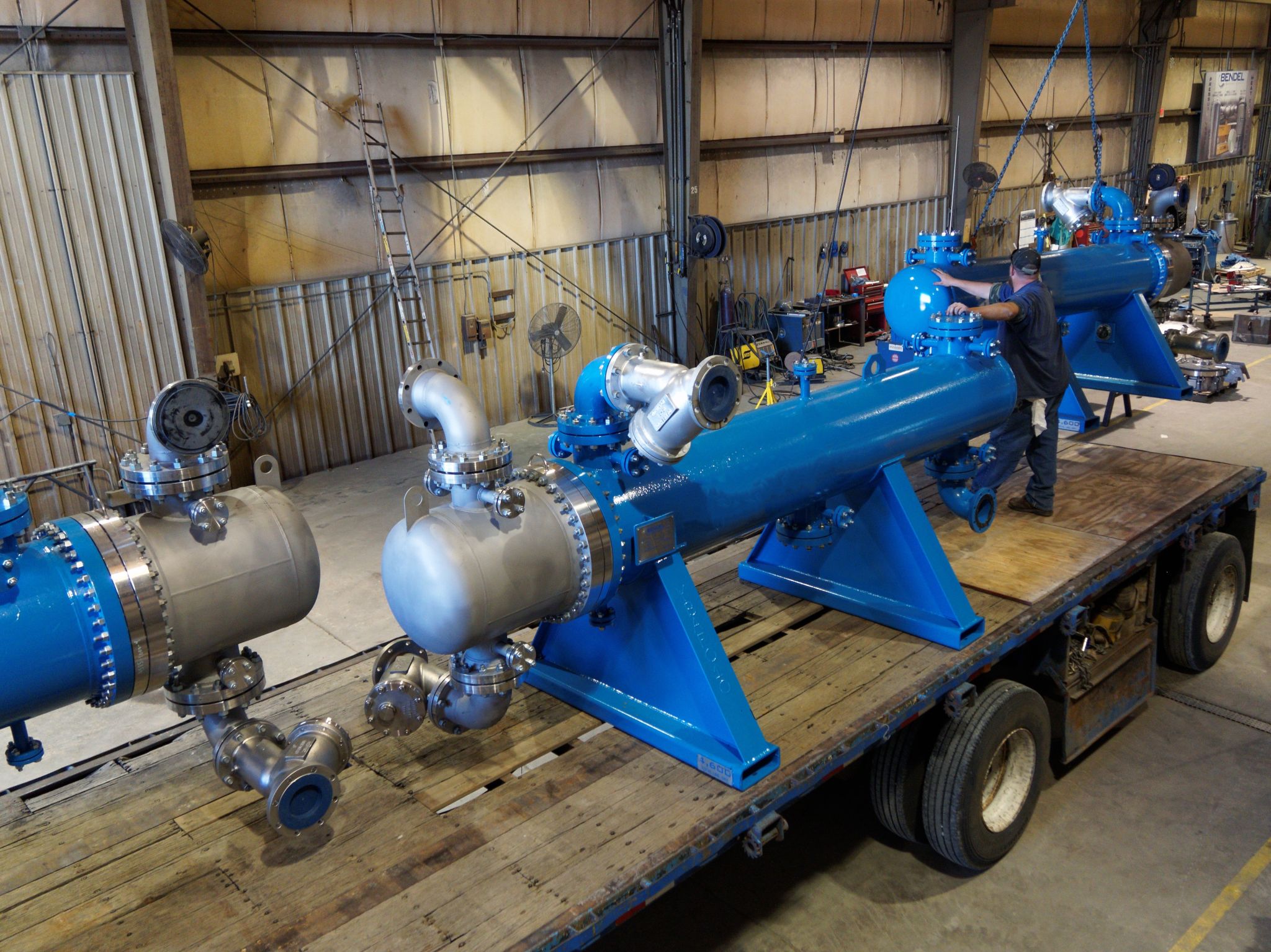
Shell and Tube Heat Exchanger
This design dominates in severe service conditions for several key reasons:
- Robust Construction: Their cylindrical shell is inherently strong and ideal for containing high internal pressures. They can be designed and fabricated to very high pressure ratings (often over 1000 bar) and temperature ratings (over 600°C) using codes like ASME BPVC.
- Large Surface Area: By increasing the number and length of tubes, a very large heat transfer surface area can be accommodated within a single unit, making them perfect for large duties (e.g., several MW).
- Design Flexibility: They can be designed with multiple tube passes and shell passes to optimize the heat transfer efficiency and velocity for a given duty.
- Material Selection: They can be constructed from a vast range of materials, including carbon steel, stainless steels, nickel alloys, and titanium, to handle corrosive fluids at high temperatures and pressures.
- Mature Technology: Their design, operation, and maintenance are well-understood globally. They are a proven, reliable technology.
Key Design Considerations for Severe Service
Within the category of shell and tube exchangers, you must choose the right type of front head, shell, and rear head to handle the specific conditions.
| Feature | Consideration for High P/T & Large Duty | Recommended Type(s) |
| Front Head (Channel) | High Pressure is the main concern. The head must safely contain the pressure. | Type B: Bonnet (Integral Cover). Simple, robust, and economical for high pressure. Type A: Removable Channel with Flange. Good for inspection but the large flange can be a weakness at ultra-high pressures. Type C: Removable Channel with Flanged Shell. Not ideal for the highest pressures due to the large shell flange. |
| Heat Exchanger Suitable for High pressure, temperature, large duties? Shell and Tube Heat Exchanger This design dominates in severe service conditions for several key reasons: Robust Construction: Their cylindrical shell is inherently strong and ideal for containing high internal pressures. They can be designed and fabricated to very high pressure ratings (often over 1000 bar) and temperature ratings (over 600°C) using codes like ASME BPVC.Large Surface Area: By increasing the number and length of tubes, a very large heat transfer surface area can be accommodated within a single unit, making them perfect for large duties (e.g., several MW).Design Flexibility: They can be designed with multiple tube passes and shell passes to optimize the heat transfer efficiency and velocity for a given duty.Material Selection: They can be constructed from a vast range of materials, including carbon steel, stainless steels, nickel alloys, and titanium, to handle corrosive fluids at high temperatures and pressures.Mature Technology: Their design, operation, and maintenance are well-understood globally. They are a proven, reliable technology. Key Design Considerations for Severe Service Within the category of shell and tube exchangers, you must choose the right type of front head, shell, and rear head to handle the specific conditions. Feature Consideration for High P/T & Large Duty Recommended Type(s) Front Head (Channel) High Pressure is the main concern. The head must safely contain the pressure. Type B: Bonnet (Integral Cover). Simple, robust, and economical for high pressure. Type A: Removable Channel with Flange. Good for inspection but the large flange can be a weakness at ultra-high pressures. Type C: Removable Channel with Flanged Shell. Not ideal for the highest pressures due to the large shell flange. Shell Type Temperature Difference between shell and tubes. Large duties often mean large temperature changes, causing thermal expansion. Type E: One Pass Shell. Most common. Type F: Two Pass Shell with Longitudinal Baffle. Rare; the baffle is prone to leakage. For large ΔT: Type J: Split Flow or Type X: Cross Flow shells reduce pressure drop and thermal stress. Rear Head Thermal Expansion. Fixing both ends of the tubes (fixed tubesheet) creates stress when temperatures differ greatly. Fixed Tubesheet (L, M, N): Simple and good for very high pressure on the tube side but can’t handle large thermal expansion. Requires an expansion bellows on the shell, which is a pressure weakness. Floating Head (S, T, P, W): Allows tube bundle to expand freely. Better for large ΔT but more complex and can have higher leakage risk. U-Tube (U): The best design for unrestricted thermal expansion. Each tube is free to expand independently. However, it’s harder to clean mechanically (bending radius is a problem) and tube-side pressure drop can be higher. |