Steps for design of heat exchanger
- Calculate the effectiveness.
- Calculate the capacity rate ratio.
- Calculate the overall heat transfer coefficient.
- Determine NTU.
- Calculate the heat transfer surface area.
- Calculate the length of the tube or heat exchanger.
For sizing a heat exchanger, several thermal phenomena should be considered first:
- Forced convection of both fluids: Convection is the transfer of heat between a wall and a flowing fluid, both having different temperatures. In the case of heat exchangers, it is called forced convection as it is caused by artificial circulation (pumps, turbines, fans…)
- Conduction: This is the transfer of heat which occurs naturally through the walls, plates and tubes. This phenomenon is based on the principle of thermal agitation without movement of material.
Thermal radiation which could be considered as negligible
1.THE CHOICE OF TECHNOLOGY
Selection of the optimum technology is linked to:
The thermal program (Required temperatures, efficiency…)
The nature of the fluids
The application
The constraints of installation and maintenance
Taking account of all these elements enables to define the type of heat exchanger (Plate heat exchanger,tubular heat exchanger…) and materials. Sometimes it is required to use a specific material that will define the choice of exchange type (e.g. compulsory titanium on an application with sea water cannot be used on all types of heat exchangers).
2.THERMAL DESIGN
2.a. Validation of
the thermal program
Once the technological choices made, we will proceed to the design of the
heat exchanger , i.e. determining its power, size and
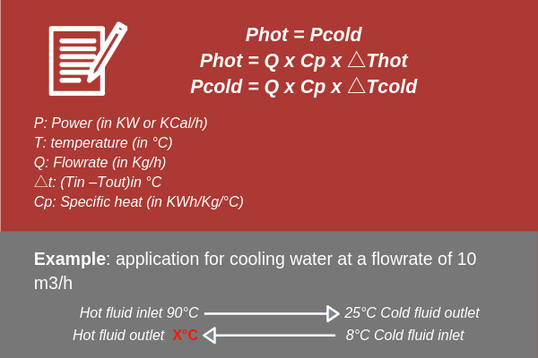
geometry. It is first necessary to validate the data of the thermal program,
with the following 3 formulas:
Thanks to those formulas, the other data can be calculated. Here we have:
i.e.
Tout = 73°C
Total power: 65,000 KCal/h or 756 KW

Tout = 73°C
Total power: 65,000 KCal/h or 756 KW
2.b. Calculation of the heating surface
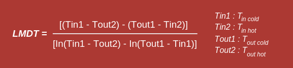
First, LMDT (Logarithmic mean temperature difference) shall be calculated. The LMDT is the logarithmic average of the temperature differences at each end of the heat exchanger.
Once LMDT and Power have been calculated, the heat exchanger calculation can be done as per the following formula:
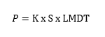
K: Heat Transfer Coefficient in KW/°C/m2 that is specific to each type of equipment and given by the manufacturer.
S : Heating area in square meters.
2.c.
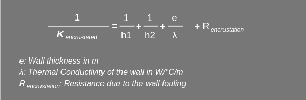
Calculation of K and incrustation
The Heat Transfer Coefficient of an heat
exchanger is given by :
h1 and h2: Local Heat exchange Coefficients calculated as per the local
geometry as well as dimensionless numbers such as Reynolds (Re), Prandlt (Pr)
and Nusselt (Nu).
Getting the Heat Transfer Coefficient (HTC
or K) enables to find the heating area and hence sizing the
heat exchanger
3. CALCULATION OF THE HEAT EXCHANGER PRESSURE DROP
A moving fluid undergoes energy losses due to friction on the walls (regular head loss) or mishaps (singular head losses) such as baffles, for example. This loss of energy, expressed in pressure drop (△P) must be compensated to allow the fluid to move.
When the heat exchanger is designed, the heat exchanger pressure drop can be calculated with different correlations determined by the characteristics of the exchange surfaces.
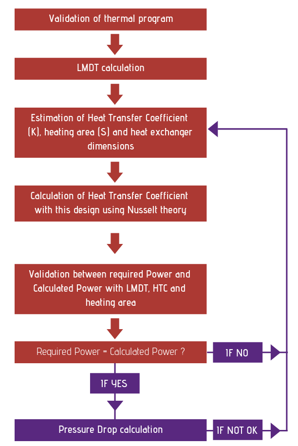
Steps 2 and 3 are made by interdependence and iterations, as shown in the summary diagram below:
HEAT EXCHANGER EFFICIENCY AND EFFECTIVENESS
We must not confuse efficiency and effectiveness. Indeed, considering no loss by radiation, therefore the effectiveness of a heat exchanger is equal to 1.
The efficiency (yield) corresponds to the following formula:
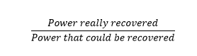
Obtaining a yield of 100% is impossible.
The yield is induced by the needs for power and temperatures of the client’s application. Hence in most cases, it is fixed upon request by the client himself.