

Dry Cooling Towers:
The dry cooling towers are designed and selected through software providing accurate data on thermal transfer rate based on which they are manufactured. The tower designed incorporates the shell and tube designed with copper tubing and aluminium foil fins. The water losses are 0.01% since, the circuits are of the closed loop type and the towers are most space saving / energy efficient once. Dry cooling towers are best suited for applications such as Furnace coil water cooling, D/G Sets, Compressors.
The fans are of aluminium die cast with adjustable pitch and are individually tested for different flow rates. Dry cooling towers are all dynamically balanced. Since, the complete fan is of Aluminium Alloy / Plastic it does not corrode when used in out door applications. Dry cooling towers are in a single unit can be provided in capacities from 1000 kw to 1500 kw and they can be multiplexed to reach many thousand or kilowatts.
process:
Dry Cooling Tower is mounted on a heavy duty channel base frame. Non corrosive fiber glass / GI panels are used for enclosure. Aero dynamically balanced high efficiency axial flow fans with low noise are used. The motors are IP 55 class with extended SS shaft. The low speed of the motor minimizes noise and increases efficiency. Motors are specially designed to withstand moisture, rain and dust.
The hot water from the diesel engine is sent to the inlet of the Dry Cooling Tower. This hot water is cooled and cold water from the outlet of the cooling tower is connected to a pump which pumps the water to the diesel engine (or any other load) to pick up the heat from the generator.
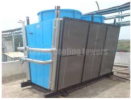
Image:
Materials:
Copper Tubes:
The best quality imported (5/8″) OD copper tubes in Level Wound Coils are used. This ensure coils with the minimum number of joints by forming a hair pin bends as well as to form a uniform wall thickness that eliminates embarrassing and expensive leaks after installation. Tubes are staggered in the path of airflow for better heat transfer efficiency.
Return Bends:
They are die-formed from thick walled tubing that is heavier than the standard tubing used in the rest of the coils. This provides the toughness and durability required in the most vital parts of the coils.
Headers:
Inlet and outlet headers are constructed of heavy wall steel pipes with shoulders formed at each brazed connection to the 5/8″ tube in the coil. This shoulders intruded with special tooling provides the strength to the brazed joint that eliminates another source of leak during transit and installation.
Mechanical Tube Expansion:
Tubes are Mechanically expanded for an optimum bond between tube and fin. This positive and controlled expansion procedure provides a clean, smooth inner tube surface for allow water pressure drop and guarantees uniform heat transfer between tube.
Applications:
- Steel Casting Foundries /Steel Plant (MS Ingot / Billet Mfg)
- Diesel / Gas generators
- Air compressor cooling / after cooler / inter cooler / jacket cooler.
- Heat Treatment Furnaces (Forging Unit)
- Special process applications
- Rubber Industries.