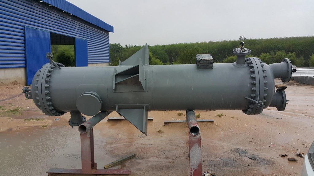
Effect of Flow Velocity in Shell and Tube Heat Exchangers
Flow velocity plays a critical role in the heat transfer efficiency, pressure drop, fouling, and mechanical integrity of a shell and tube heat exchanger. Below is a detailed breakdown of its effects:
1. Heat Transfer Efficiency
Higher Velocity → Better Heat Transfer
- Increased turbulence reduces the thermal boundary layer, improving heat transfer.
- Reynolds number (Re) increases, shifting flow from laminar to turbulent (better mixing).
- Typical recommended velocities:
- Shell side: 0.3 – 1.5 m/s
- Tube side: 1 – 3 m/s
Too High Velocity:
- No significant improvement in heat transfer beyond a certain point.
- Excessive pressure drop (increases pumping cost).
2. Pressure Drop (ΔP)
ΔP ∝ Velocity² (Square Relation)
- Higher velocity = Much higher pressure drop (Darcy-Weisbach equation).
- Impact on operating costs:
- More pump/fan power needed.
- Risk of cavitation (if velocity exceeds limits).
Recommended Limits to Avoid Excessive ΔP:
| Side | Max Velocity (m/s) |
| Tube Side | 2 – 3 (liquids), 20 – 30 (gases) |
| Shell Side | 1 – 1.5 (liquids), 10 – 15 (gases) |
Fouling & Erosion
Low Velocity → Fouling Risk
- Particulate deposition increases (sludge, scale, biofilms).
- Stagnant zones promote corrosion.
High Velocity → Erosion Risk
- Tube/shell wall thinning (especially near bends & baffles).
- Sand, slurries, and abrasive fluids accelerate wear.
Optimal Velocity for Fouling Control:
- Tube side: 1.5 – 2.5 m/s (liquids)
- Shell side: 0.5 – 1 m/s (liquids)
4. Vibration & Mechanical Damage
- Excessive shell-side velocity can induce flow-induced vibration (FIV).
- Causes tube fatigue, fretting wear, and failure.
- Critical velocity depends on tube material, support spacing, and fluid density.
- Remedies:
- Use baffle cuts (20-25%) to reduce cross-flow velocity.
- Anti-vibration bars or helical baffles for stabilization.
5. Pumping Power & Energy Costs
- Higher velocity = More energy consumption (pump/fan power ∝ ΔP).
- Trade-off:
- Increase velocity → Better heat transfer but higher ΔP.
- Decrease velocity → Lower ΔP but risk of fouling & poor heat transfer.
Economic Optimization:
- Find a balance where heat transfer gains justify pumping costs.
6. Design Considerations for Optimal Velocity
Tube Side
- Liquids: 1 – 3 m/s
- Gases/Vapours: 10 – 30 m/s
- Two-phase flow: 5 – 15 m/s
Shell Side
- Liquids: 0.3 – 1.5 m/s
- Gases: 5 – 15 m/s
Baffle Spacing Impact
- Wider baffle spacing → Lower shell-side velocity (but poor heat transfer).
- Narrower baffle spacing → Higher velocity (better heat transfer but higher ΔP).
7. Summary of Effects
| Velocity Impact | Too Low | Too High | Optimal Range |
| Heat Transfer | Poor (laminar flow) | No extra benefit | 1 – 3 m/s (tube), 0.5 – 1.5 m/s (shell) |
| Pressure Drop | Low (good) | Very high (costly) | Balance with heat transfer |
| Fouling | High risk | Low risk | 1.5 – 2.5 m/s (tube) |
| Erosion | Negligible | Severe risk | Avoid >3 m/s (abrasive fluids) |
| Vibration | None | Tube damage possible | Baffle design critical |
8. Practical Recommendations
For liquids: 1.5 – 2.5 m/s (tube), 0.5 – 1.5 m/s (shell)
For gases: 10 – 30 m/s (tube), 5 – 15 m/s (shell)
Fouling fluids: ≥1.5 m/s (tube side) to prevent deposits.
High ΔP systems: Reduce velocity or increase tube diameter.
