
Working Principle of Dry Fluid Cooler
A Dry Fluid Cooler works on the principle of sensible heat transfer. It uses ambient air to cool a process fluid without the fluid and air ever coming into direct contact. The heat is rejected solely through the transfer of thermal energy (sensible heat) from the hot fluid to the cooler air across a metal barrier.
Think of it exactly like a car radiator: hot coolant flows through tubes, and a fan blows cool air over those tubes to remove the heat before the coolant cycles back to the engine.
Step-by-Step Working Principle
The process can be broken down into the following key steps:
Step 1: Hot Fluid Inlet
A pump circulates the hot process fluid (e.g., water, water-glycol mix, oil, or other industrial fluids) from the heat-generating equipment (like machinery, a data center server rack, or a power generator) into the inlet header of the dry cooler’s heat exchanger coil.
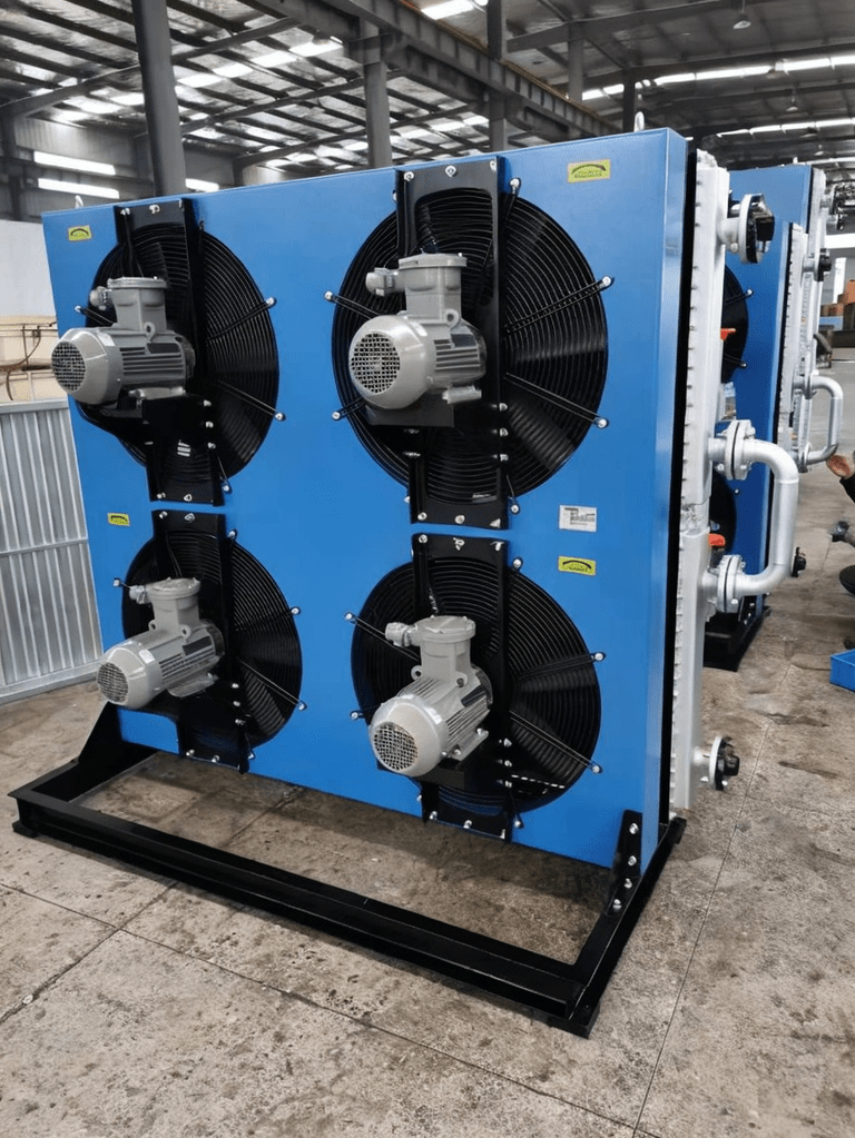
Step 2: Heat Exchange via Finned Coils
The hot fluid is distributed through a network of tubes, which are externally bonded to many thin metal fins. This finned-tube design is crucial as it dramatically increases the surface area exposed to the air.
- The fluid flows inside the sealed tubes.
- Meanwhile, one or more large, powerful fans force ambient air across the outside of the finned tubes.
Step 3: Sensible Heat Transfer
This is the fundamental physical process:
- The hot process fluid inside the tubes has a higher temperature than the cooler ambient air outside.
- Heat naturally flows from a hotter medium to a colder medium.
- This thermal energy (heat) conducts through the metal wall of the tube and fins and is carried away by the moving air.
- Crucially, this is only a transfer of energy. No mass is exchanged. The process fluid remains entirely contained within its closed loop, and no evaporation occurs.
Step 4: Cooled Fluid Outlet
After passing through the coil and giving up its heat, the now-cooled process fluid collects in the outlet header and is pumped back to the industrial process to absorb more waste heat. This creates a continuous, closed cooling loop. Step
5: Warm Air Exhaust
The air, having absorbed the thermal energy from the fluid, becomes warmer and is discharged to the atmosphere. This air is simply warmer; it does not contain any moisture added from the process or any chemical contaminants.
The Critical Concept: Approach Temperature
A key performance metric for a dry cooler is the Approach Temperature.
- Definition: How close the cooled process fluid temperature can get to the ambient air temperature.
- Formula: Approach Temperature = Outlet Fluid Temperature – Ambient Dry-Bulb Temperature
- Example: If the cooled fluid leaves the dryer at 95°F (35°C) and the outside air temperature is 85°F (29.4°C), the approach temperature is 10°F (5.6°C).
Why it matters: A smaller approach indicates a larger, more efficient (and more expensive) heat exchanger. Dry coolers can only cool the fluid to a temperature above the ambient dry-bulb temperature. This is their primary limitation compared to evaporative coolers (like cooling towers), which can cool to a temperature closer to the lower ambient wet-bulb temperature.
Principle in Action: Fan Control
The principle of heat transfer drives the control systems:
- On/Off or Staging: Multiple fans can be turned on or off in stages based on fluid temperature.
Variable Frequency Drive (VFD): This is the most efficient method. The fan speed is modulated based on the temperature of the returning process fluid. As the ambient air gets cooler (e.g., at night or in winter), the fans slow down, saving significant energy.
- Conversely, on a hot day, they run at full speed to maximize airflow and heat rejection.