

Introduction:
Dummy Load Heat Exchangers include a resistive sodium nitrite resistive load directed by insulating tubes to flow in the load. The cooling circuit includes a primary circuit having inlet and outlet thermistors, and a secondary cooling circuit coupled thereto by a liquid to liquid heat exchanger. In the control circuit, the thermistors are serially connected in a bridge circuit, unbalances in the bridge being detected to directly control a motor for controlling a valve in series in the secondary loop. A pair of slower moving valves in series and shunt respectively in the secondary loop is controlled upon the movement of the directly controlled valve to a limit position.
Design And Process Of Dummy Load Heat Exchangers:
Mainstream dummy loads for HF bands are limited to 1 kW of power capabilities. If you need more power handling this design is a way to get into the 4-5 kW regions with regularly available components. Used are 18 times 100 Ohm high power flange mount resistors. Care should be given to adequate cooling of the resistors in order to keep the mounting tab temperature below 100 degree °C. With an ambient temperature of 25 degree this will lead to a heat sink with heat sink-ambient thermal resistance below 0.02 °C/Watt. To achieve this with standard heat sink design a very big heat sink with many vines is needed, even with additional forced air cooling. Besides power capability of more than 4 kW continues this dummy load will provide adequate return loss across all HF bands below 30MHz. Due to the rather high self capacitance of the flange mount resistors (approx. 6 pF) return loss will deteriorate quickly above 50 MHz
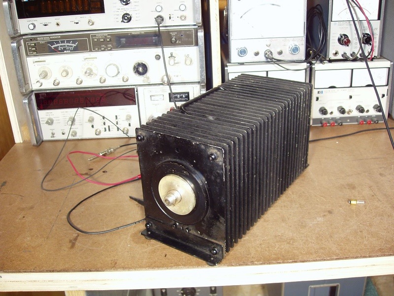
Image Of Dummy Load Heat Exchangers:

Specification Of Dummy Load Heat Exchangers:
- 10U Chassis with guide track, which can be installed in a standard rack.
- Install 800W heating units, which compose of heaters and fins. 5 sets in total. Each set can be modified its heating power, which resolution is 100W.
- In the chassis, there are 4~6 fans in the inlet and their RPM are controlled by 1 set of PWM meter.
- Maximum flow rate: 1000 CFM, which is controlled by fan’s voltage; resolution: 50 CFM
- The flow rate of chassis can be calculated by System Resistance Curve (differential pressure-airflow rate).
- 12 points of temperature measurement in the chassis inlet; 24 points of temperature measurement in the chassis outlet; there are 6 sets of temperature measurement in total.
Accuracy: ±0.5°C; reading: 0.1°C; with digit display and RS-485 interface. - Power measurement: Voltage accuracy: ±1.0%; current accuracy: ±1.0%; power accuracy: ±1.0%; 2 sets in total; with digit display and RS-485 interface. Range: 0 ~300 V and 0~5 Amp; maximum power: 1500 VA.
Applications Of Dummy Load Heat Exchangers:
- Quiet operation
- Interlock
- Mounted on casters for ease of mobility and compact size
- Options for the units include Internal or remote load operation, calorimeter, 50 Hz operation